current position: Home > News > News > Industry Information
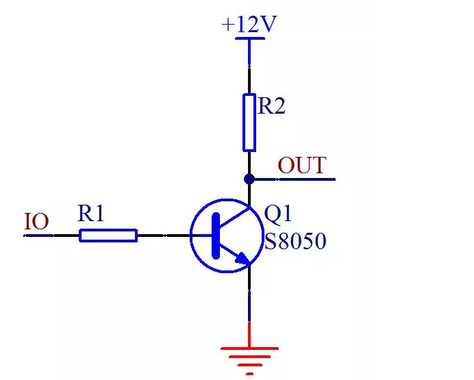
There are two most common applications for the switching characteristics of transistors in digital circuits: one is control application and the other is drive application. The so-called control is introduced in Figure 3-7. We can indirectly control the on and off of the small light behind by controlling the base of the triode through the single-chip microcomputer. The usage is basically familiar to everyone. Another control is to control the conversion between different voltages. For example, our single-chip microcomputer is a 5V system, and it needs to be connected to a 12V system. If the IO is directly connected to the 12V voltage, the single-chip microcomputer will be burned out, so we add a triode, The working voltage of the triode is higher than the voltage of the IO port of the single-chip microcomputer, and the 5V IO port is used to control the 12V circuit, as shown in Figure 3-8.

Figure 3-8 Transistor realizes voltage conversion
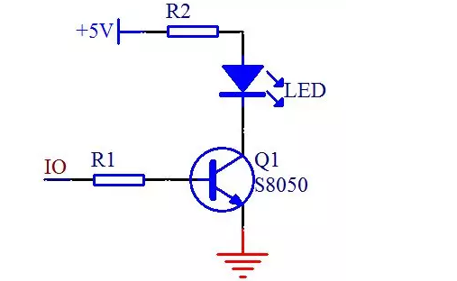
The upper LED light in Figure 3-9 is the same as the LED light we talked about in the second lesson. When the IO port is high, the small light is off, and when the IO port is low, the small light is on. So the circuit below, according to this reasoning, when the IO port is at a high level, there should be current flowing and lighting the small light, but in fact it is not that simple.
The single-chip microcomputer is mainly a control device, with the characteristics of four or two. Just as a lever must have a fulcrum, if you want to prop up the entire earth, you must have a fulcrum that can withstand strength. The IO port of the single-chip microcomputer can output a high level, but its output current is very limited. When the ordinary IO port outputs a high level, there is only a current of tens to hundreds of uA, which is less than 1mA, so it is not Turn on this small LED light or the brightness is very low. At this time, if we want to light up the LED at a high level, we can use a transistor to handle it. This type of transistor on our board can pass a current of 500mA, and some The current through the triode is still larger, as shown in Figure 3-10.

Figure 3-10 Transistor driving small LED lights
In Figure 3-10, when the IO port is at high level, the triode is turned on. Because of the current amplification effect of the triode, the c-pole current can reach more than mA, and the small LED light can be successfully lit.
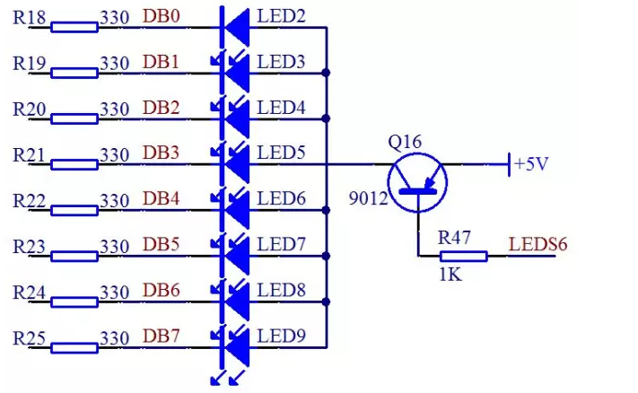
Although we use the low level of the IO port to directly light the LED, can the input current be large when the IO port of the single-chip microcomputer is used as a low level? I think everyone can guess it, of course not. The current carrying capacity of the IO port of the single-chip microcomputer is not exactly the same for different models. As for the STC89C52, page 81 of the official manual has an introduction to the electrical characteristics. The operating current of the entire single-chip microcomputer should not exceed 50mA, and the total current of a single IO port should not exceed 6mA. Even though some enhanced 51 IO ports can withstand a higher current, which can reach 25mA, they are still limited by the total current of 50mA. Then let's look at the part of the circuit of the 8 LED lights in the circuit diagram, as shown in Figure 3-11.

Figure 3-11 LED circuit diagram (1)
Here we have to learn to look at a knowledge point of the circuit diagram. All the wires on the lower side of the LED on the right side of the circuit diagram are finally connected to a thick black wire. Please note that this place is not actually completely connected together, but a whole This kind of bus drawing method, after drawing this kind of line, it means that this is a bus structure. All nodes with the same name are connected in a one-to-one correspondence, and other nodes with different names are not connected together. For example, DB0 on the left and DB0 under the rightmost LED2 light on the right are connected together, but not with other lines such as DB1.
So let's take out the part that needs to be explained in Figure 3-11 separately, as shown in Figure 3-12.

Figure 3-12 LED circuit diagram (2)
Now let’s calculate through the circuit diagram of 3-12, the voltage of 5V minus the voltage drop of the LED itself, minus the voltage drop between the transistor e and c, the current-limiting resistor is 330 ohms, then the voltage of each branch The current is about 8mA, so if all 8 LEDs are lit at the same time, the total current is 64mA. In this way, if it is directly connected to the IO port of the single-chip microcomputer, the single-chip microcomputer must not be able to bear it. Even if it can bear it for a short time, it will be unstable when working for a long time, and even cause the single-chip microcomputer to burn out.
Some students will propose ways to increase the current-limiting resistance to reduce this current. For example, if it is changed to 1K, the current is less than 3mA, and the total current of 8 channels is about 20mA. First of all, reducing the current will cause the brightness of the small LED lamp to dim. The brightness of the small lamp may not be related, but because our same circuit is connected to the digital tube, we will talk about the digital tube and dynamic display, if the brightness of the digital tube is not enough If it does, the visual effect will be poor, so the method of reducing the current is not advisable. Secondly, for the single-chip microcomputer, it mainly plays a control role. The ability of current input and output is relatively weak. The total current of the 8 ports of P0 is also limited, so if you connect one or two small LED lights to observe, you can barely direct Use the IO port of the single-chip microcomputer to connect, but connect multiple small lights. Considering from the perspective of actual engineering, it is not recommended to connect the IO port directly. So what should we do if we want to control multiple small LED lights with a single chip microcomputer?
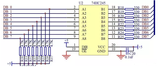
In addition to the triode, there are actually some driver ICs. These driver ICs can be used as the buffers of the single-chip microcomputer. They are only current drive buffers and can not have any logic control effect. For example, the 74HC245 chip used on our board. Logically, it has no other function, that is, it is used as a current buffer. By checking its data sheet, it is no problem for 74HC245 to work stably at 70mA current, which is much larger than the 8 IO ports of the single-chip microcomputer, so we can use it as a current buffer. Connect the small lamp and the IO port as a buffer, as shown in Figure 3-13.

Figure 3-13 74HC245 function diagram
Let's analyze it from Figure 3-13. Needless to say, VCC and GND need not be mentioned. Careful students will find that there is a 0.1uF decoupling capacitor.
74HC245 is a two-way buffer, 1 pin DIR is the direction pin, when this pin is connected to a high level, all the voltages of the B numbers on the right are equal to the voltages corresponding to the A numbers on the left. For example, if A1 is high level, then B1 is high level, A2 is low level, B2 is low level and so on. If the DIR pin is connected to a low level, the effect obtained is that the voltage of the number A on the left will be equal to the voltage corresponding to the number B on the right. Because the control terminal in our place is connected to port P0 on the left side, we require that B be equal to A, so the 5V power supply directly connected to pin 1 is high level. In Figure 3-13, there is a row of resistors R10 to R17 that are pull-up resistors. The usage of this resistor will be introduced later.
There is also the last enable pin 19, pin OE, which is called output enable. There is a horizontal line on this pin, indicating that it is low-level active. When the low-level is connected, the 74HC245 will be bidirectional as mentioned above. The function of the buffer, if OE is connected to a high level, then no matter how DIR is connected, the A and B pins are irrelevant, that is, the 74HC245 function cannot be realized.
It can be seen from the figure 3-14 below that the P0 port of the single-chip microcomputer and the A terminal of the 74HC245 are directly connected. In this place, some students have a question, that is, we obviously added a transistor driver to the power supply VCC, why we need to add a 245 driver chip. Everyone has to understand a truth here. From the positive pole to the ground through the device, there must be current before it can work normally. If any position in the circuit is disconnected, there will be no current, and the device will not participate in the work. Secondly, the same as the water flow, the thickness of the current water pipe from the positive pole to the negative pole of the power supply must meet the requirements. If the pipe at any position is too thin, a bottleneck effect will occur. The current will be restricted and reduced at the thin pipe in the entire path. At each position of the circuit path, it is necessary to ensure that the channel is sufficiently unblocked. The function of this 74HC245 is to eliminate the bottleneck of the single-chip IO link.

Figure 3-14 The connection between the single-chip microcomputer and 74HC245
This article tags:The,Application,Transistor,the,Digital,Circuit,Single,Chip The last:The birth of the largest chip The last:The rise of fingerprint recognTel: 0755-83948880
Fax: 0755-83948881
E-mail: sales@sunshineic.com
Add: RM 603, Building 405, Shangbu Industrial Area, Zhenxing RD, Futian District , Shenzhen, China
 Wechat QR code
 Phone QR code